Introduction
So over the last year I've been working on a 12x12 RGB led Matrix Frame which has ground to a halt on the software side, as I couldn't find a decent way to send data to the frames from either a server or an app.
I tried Firmata with Golang with Gobot and while great over TCP for small payloads, I/O ports on off etc.. It just couldn't handle the 500 odd bytes I need to throw at it for each of the images. And the Gobot implementation of NeoPixels on the ESP8266 isn't quiet there yet.
So I discovered OSC about a month ago and had a look at the examples and left it at that. Watched a stream by theOtherLoneStar last night, I decided I'd give it another go as he made it look so easy !!
OSC (Open Sound Control) is a protocol that uses UDP to communicate between computers, sound synthesizers, multimedia devices and now IOT devices. Its fast, flexible and has been used for years in sound/media fields and is very well supported. More information about it can be found here
So over the next couple of posts I'll details how to use OSC via python to send data to an ESP8266 OSC Server.
The eventual goal of this development is to have an app on the phone which allow me to send images (12x12 pixels) to the frame and allow me to draw live.
Requirements
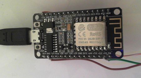
ESP8266
I'm using a Wemos D1 compatible device. As well as the esp8266 wifi libraries you will also need to install the OSC library from the Arduino IDE
Python
After trying out a few libraries for Python I settled on SimpleOSC
Just follow the installation instructions on the site.
A Simple test
First up we have a simple LED blink test.
The Arduino code starts an OSC Server on UDP port 8888 and waits for either a 0 or 1 to be sent to /led to turn the internal led on or off. Nothing spectacular but its to prove that the system works.
The python code acts as the client send the payload to turn the led on or off. While this is python at the moment it can be anything that support OSC.
Python Code, Client
"""Example OSC client

this program sends a led on/off request every second for 10 seconds to an esp8266
"""

import time
from osc import OSCMessage, OSCClient, OSCBundle

client = OSCClient('x.x.x.x', 8888) # set Ip address to your ESP IP address
# create osc message with address '/led' the inbuilt led

messageOn = OSCMessage(address='/led')
messageOn.add(0)

messageOff = OSCMessage(address='/led')
messageOff.add(1)

# create osc bundle and add a message
bundle = OSCBundle()
bundle.add( messageOn )

bundle2 = OSCBundle()
bundle2.add( messageOff )

for x in range(10):
    client.send( bundle )
    time.sleep(1)
    client.send( bundle2 )
    time.sleep(1)
Arduino Code, Server
/*---------------------------------------------------------------------------------------------

  Open Sound Control (OSC) library for the ESP8266/ESP32

  Example for receiving open sound control (OSC) bundles on the ESP8266/ESP32
  Send integers '0' or '1' to the address "/led" to turn on/off the built-in LED of the esp8266.

  This example code is in the public domain.

--------------------------------------------------------------------------------------------- */
#ifdef ESP8266
#include
#else
#include
#endif
#include
#include
#include
#include

char ssid[] = "myssid";          // your network SSID (name)
char pass[] = "mypassword";       // your network password

// A UDP instance to let us send and receive packets over UDP
WiFiUDP Udp;
const IPAddress outIp(10,40,10,105);        // remote IP (not needed for receive)
const unsigned int outPort = 9999;          // remote port (not needed for receive)
const unsigned int localPort = 8888;        // local port to listen for UDP packets (here's where we send the packets)

OSCErrorCode error;
unsigned int ledState = LOW;              // LOW means led is *on*

#ifndef BUILTIN_LED
#ifdef LED_BUILTIN
#define BUILTIN_LED LED_BUILTIN
#else
#define BUILTIN_LED 13
#endif
#endif

void setup() {
  pinMode(BUILTIN_LED, OUTPUT);
  digitalWrite(BUILTIN_LED, ledState);    // turn *on* led

  Serial.begin(115200);

  // Connect to WiFi network
  Serial.println();
  Serial.println();
  Serial.print("Connecting to ");
  Serial.println(ssid);
  WiFi.begin(ssid, pass);

  while (WiFi.status() != WL_CONNECTED) {
    delay(500);
    Serial.print(".");
  }
  Serial.println("");

  Serial.println("WiFi connected");
  Serial.println("IP address: ");
  Serial.println(WiFi.localIP());

  Serial.println("Starting UDP");
  Udp.begin(localPort);
  Serial.print("Local port: ");
#ifdef ESP32
  Serial.println(localPort);
#else
  Serial.println(Udp.localPort());
#endif

}

void led(OSCMessage &msg) {
  ledState = msg.getInt(0);
  digitalWrite(BUILTIN_LED, ledState);
  Serial.print("/led: ");
  Serial.println(ledState);
}

void loop() {
  OSCBundle bundle;
  int size = Udp.parsePacket();

  if (size > 0) {
    while (size--) {
      bundle.fill(Udp.read());
    }
    if (!bundle.hasError()) {
      bundle.dispatch("/led", led);
    } else {
      error = bundle.getError();
      Serial.print("error: ");
      Serial.println(error);
    }
  }
}
Next Steps
For part 2 I'll connect up the RGB LED Matrix (12x12, 144 LEDs) to the ESP and send some OSC Blob data which should allows us to send a full frame image to the Matrix.
